LTspice Tutorial: Part 1
The LTspice Tutorial below will talk you through how to get started with LTspice®, the free circuit simulation package from Analog Devices.
To download LTspice, go to the Analog Devices Home Page and search for LTspice. Navigate to the LTspice download page and download the installation file. You can either register to get notifications of updates, or just download the package. If you do not register, you can still update the package as often as you like.
Download the .msi file to a directory of your choice.
Run the .msi file, accept the license agreement and install LTspice.
LTspice should start automatically and place an icon on your desktop.
Once in LTspice, click on Tools -> Update Components to ensure you have the latest updates. It is worth repeating this step every time you use LTspice to ensure you have the latest models loaded.
LTspice has models of most of Analog Devices' analogue part numbers as well as Example Circuits to get you started. Example Circuits are ready made circuits including the desired component and all the surrounding resistors, capacitors and inductors to enable you to immediately start evaluating it.
It is advisable to create a separate directory to store your LTspice files so you do not overwrite the original jig files.
To start, we are going to design a non inverting amplifier with a gain of 10 and a 1kHz 1V sinewave input, based on the LT1012 op amp.
Double clicking on the desktop icon brings up the page shown in Figure 1.
Figure 1
To bring up the Example Circuit select File -> New Schematic then press the
 icon and navigate to the component you need, then click 'Open Example Circuit', as shown in Figure 2
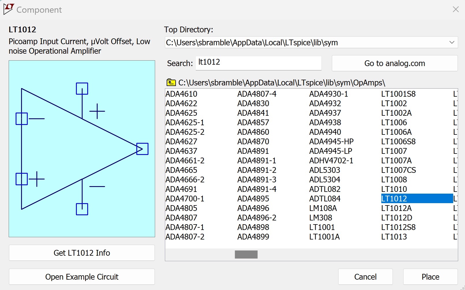
Figure 2
It should look like Figure 2a
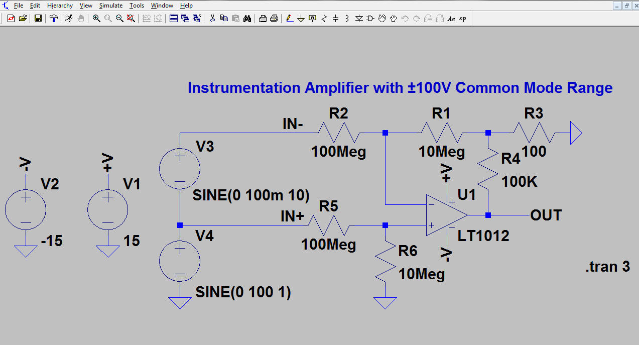
Figure 2a
Save this file to your chosen directory.
To open the datasheet for the part, right click on the part and Select 'Find on Analog.com'.
The background of the schematic can be changed to another colour. To do this go to Tools -> Colour Preferences then click on the Schematic tab, then select Background from the dropdown menu and change the colour using the sliders. Other colours of the schematic can also be changed using the same method.
Likewise, by selecting the Waveform tab, the colour of the traces and background can be changed.
On the schematic, the pen thickness can be changed by selecting Tools -> Settings and selecting the Schematic tab then changing the Pen Thickness box. This makes the schematic easier to see on certain monitors. Similarly, by selecting the Waveforms tab, the trace thickness and cursor widths can be changed.
We are going to edit this schematic to get a non inverting amplifier as specified earlier.
LTspice has been rewritten to make the keyboard shortcuts more intuitive. However, the old keyboard shortcuts can still be used. Select Tools -> Settings then select the Schematic tab, then click the Keyboard Shortcuts button. This will allow the user to use the new shortcuts (select Restore Defaults) or the old shortcuts (Restore LTspice Classic Values). Both are show in Figure 3 below
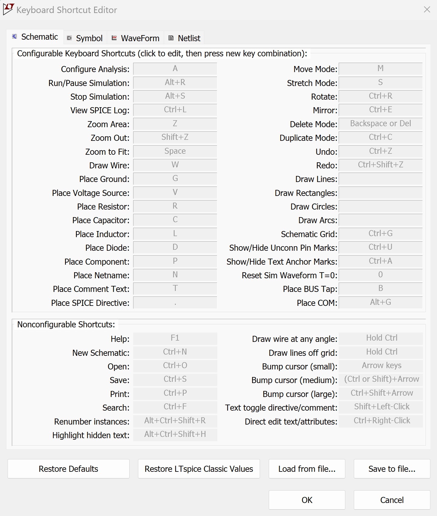
Figure 3a - New LTspice keyboard Shortcuts
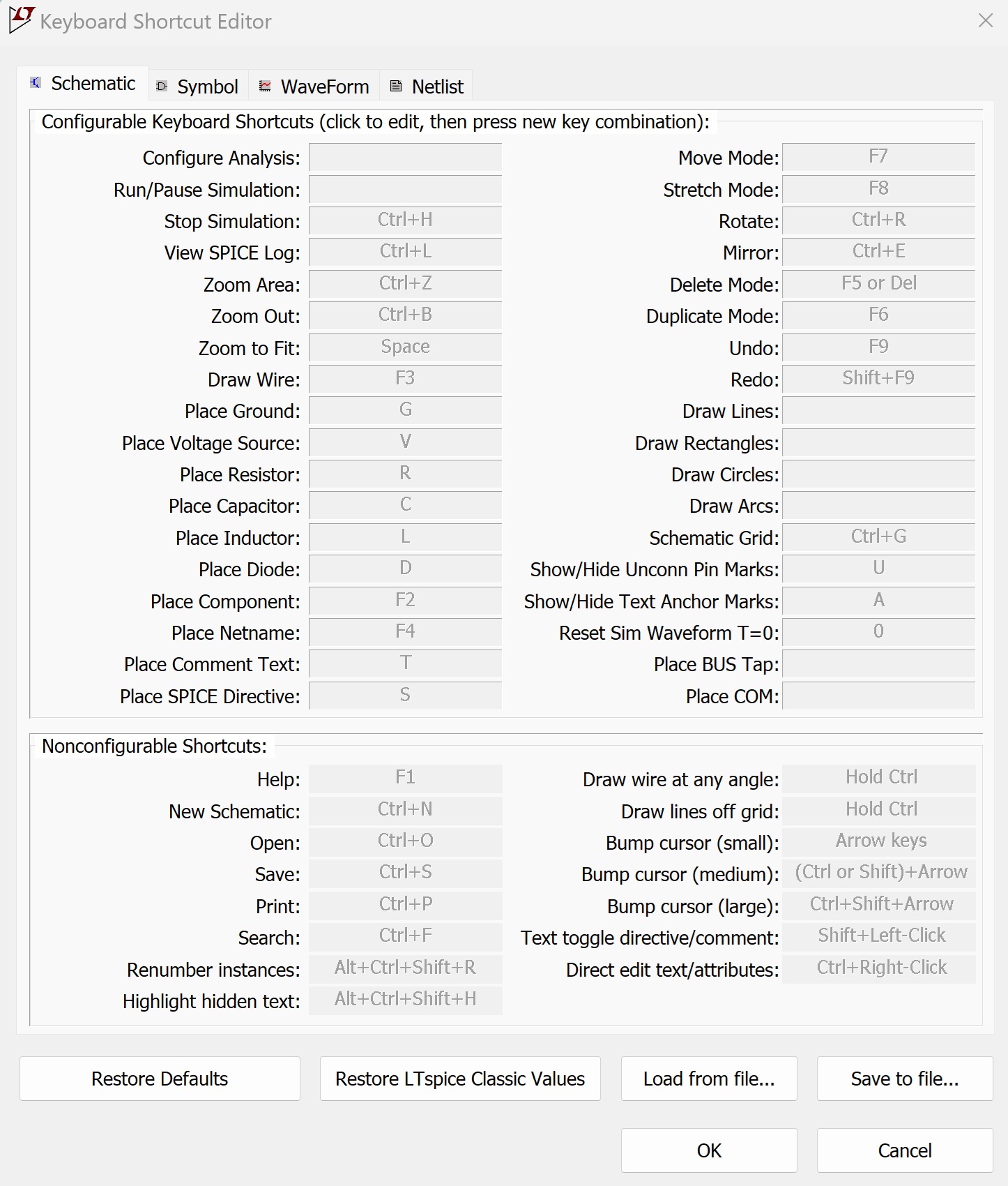
Figure 3b - Classic LTspice keyboard Shortcuts
In addition to the commands above, the LTspice toolbar shown in Figure 4 allows us to insert components and edit the schematic.
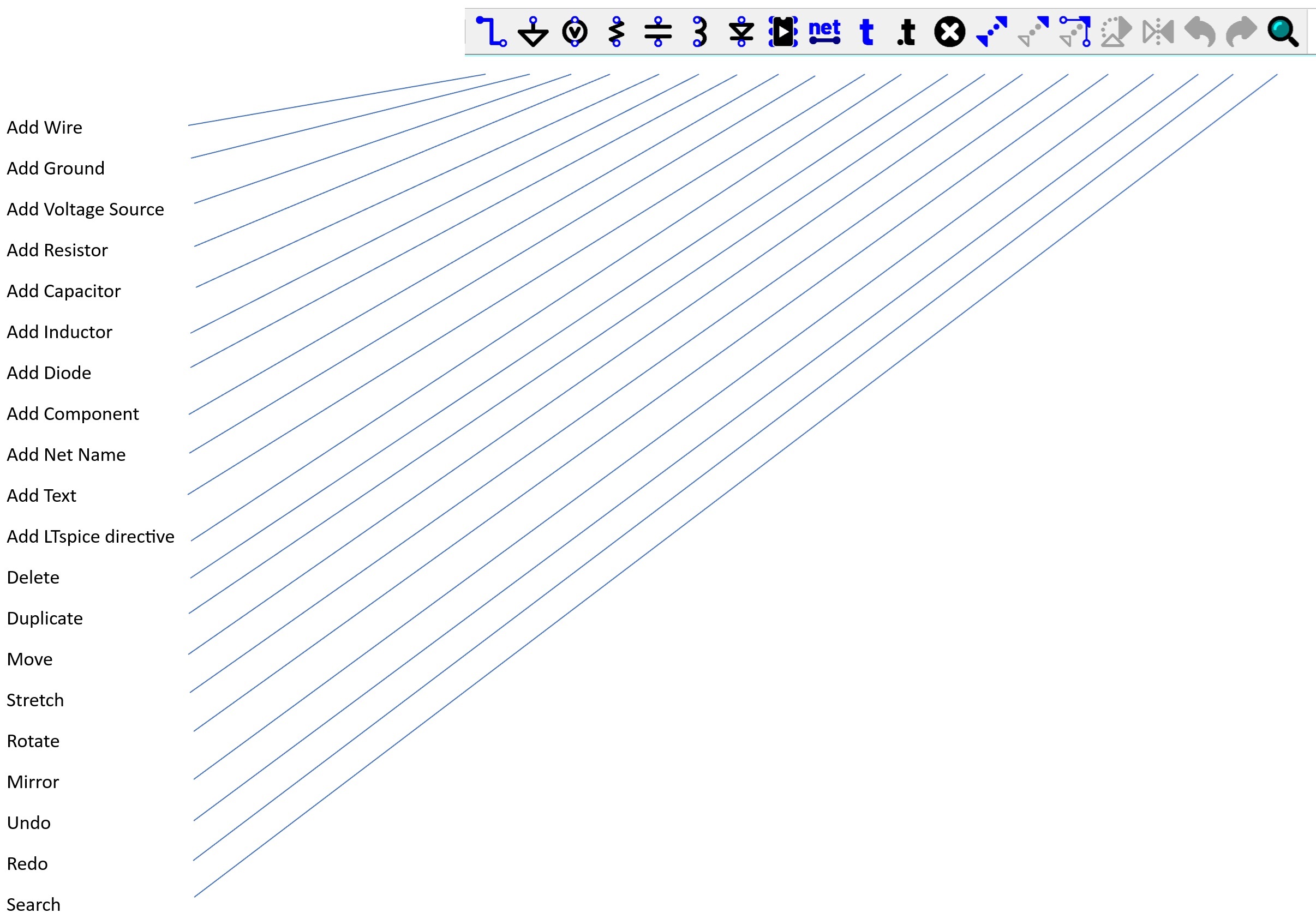
Figure 4
In the schematic above, V1 and V2 are the +/-15V supply to the LT1012. We also want to keep V4, the input signal as well as the op amp.
Using the shortcut keys and the toolbar construct the schematic shown in Figure 4. Large areas of circuit can be deleted/moved/copied by selecting the appropriate <F> key, holding down the left hand mouse button and highlighting that part of the circuit.
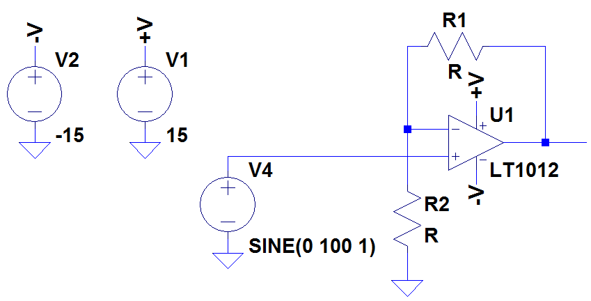
Figure 5
Note that R1 and R2 are generic resistors with no value. To change the value of any component in LTspice, right click over the component to bring up the basic component properties. Holding down the <CTRL> key and right clicking brings up a more comprehensive list of properties. To change the values of R1 and R2, right click over these components and type 10k into the Resistance box.
We now need to modify V4 to give us a sinewave of 1kHz. Right click over V4 and it will bring up the box shown in Figure 6
We now need to modify V4 to give us a sinewave of 1kHz. Right click over V4 and it will bring up the box shown in Figure 6
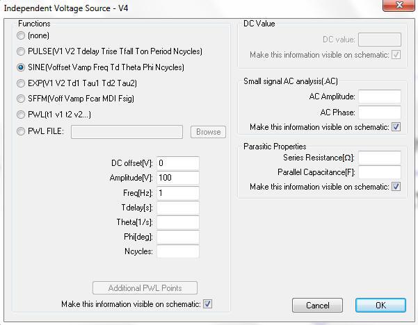
Figure 6
This dialogue box allows us to choose whether V4 is a DC voltage, Pulse, Sinewave, Exponential, Single Frequency FM or Piece Wise Linear waveform. The only parameters we need to modify are Amplitude (change this to 1) and Freq (change this to 1k).
Incidentally, LTspice recognises 'M' to mean 'milli' so setting the frequency to 1M will produce a sinewave of 1milliHertz. If a frequency of 1MHz is desired, either use 1000k or 1MEG.
Click OK to return to the schematic.
We now need to add some labels to the circuit which makes probing much easier. Click on the Add Net Name icon and add IN to the input and OUT to the output. Your circuit should look like Figure 7.
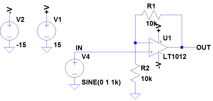
Figure 7
To set the simulation conditions, click on Simulate -> Configure Analysis and enter 10ms in the Stop Time box as shown in Figure 8.
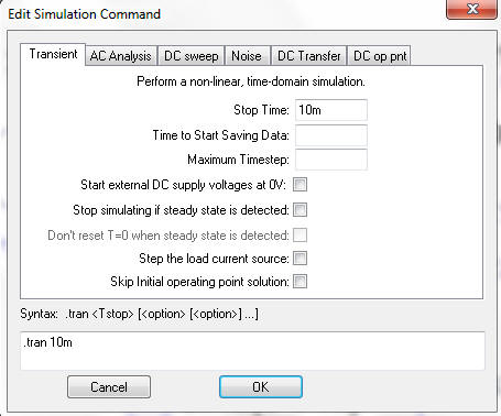
Figure 8
We are now ready to simulate the circuit. Save the file.
Click on the Run/Pause icon in the toolbar as shown in Figure 9
Click on the Run/Pause icon in the toolbar as shown in Figure 9

Figure 9
The screen will divide showing the schematic in one half and the simulation window in the other. Click the mouse anywhere in the schematic window. Moving the mouse over certain parts of the circuit will highlight either a voltage probe or current probe.

Voltage Probe

Current Probe
Hover the mouse over the output of the op amp and click when the probe appears to show the voltage at the output of the op amp. Repeating this process at the input of the op amp shows the input voltage. The resultant waveform screen should look like Figure 10
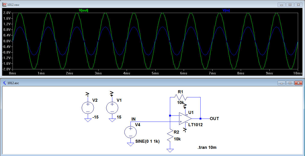
Figure 10
LTspice Tutorial 1: Other Tips and Tricks
All circuits must have a ground.
Drawing a wire straight through several components is an easy way of connecting the components in series.
If you need to plot a differential voltage, move the mouse to the positive node of the voltage to be measured and once the probe symbol has appeared, left click the mouse then drag the probe to the negative node. The probe colour will change from red to black. Release the mouse and the differential voltage will be displayed.
If you want to plot multiple waveforms with respect to a node other than ground, navigate to that node, right click the mouse and the following list of options will appear:
Select 'Mark Reference'. Thereafter all plots will be referenced with respect to that node.
Sometimes it is convenient to have 2 plot panes, especially when comparing 2 voltages of very different amplitudes. To create multiple plot panes, move the mouse to the plot pane, right click and select Add Plot Pane. Left clicking on a specific pane loads the probe results into that pane. Left clicking on the waveform icon (e.g. V(out)) and dragging the icon to the other pane, moves the waveform to the other pane.
To remove a waveform from the plot pane, hit the <F5> key and delete the appropriate waveform logo at the top of the plot pane. As with the schematic editor, the <F9> key undoes the last action performed in the plot pane.
Holding down the ALT key and left clicking over a wire plots the current in the wire.
Holding down the ALT key and left clicking over a components displays the instantaneous power in that component.
The latest versions of LTspice (LTspice XVII and higher) allow the use of multiple monitors, so the schematic can be displayed on one monitor, while the plot results are displayed on a second monitor. Right click in the Schematic Window and select 'Float Window'. The Schematic Window can now be moved between screens. The same can be done with the Plot Window.
The toolbar can, however, only address non floating windows, so the Running Man symbol is greyed out when windows are floating. To run the simulation, select the Schematic Window, right click then select 'Run'.
Want to know more?
Please see LTspice Tutorial: Part 2
LTspice is a registered trademark of Analog Devices Inc
Sitemap: www.simonbramble.co.uk/sitemap
© Copyright Simon Bramble