Op Amp Noise Analysis
This article explains how to calculate the output noise of an op amp circuit, backed up with simulations in LTspice®.
Resistor Noise
A resistor produces noise according to the equation
Resistor Noise
A resistor produces noise according to the equation
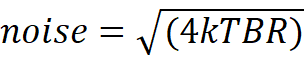
where
k = 1.38 x 10⁻²³ (Boltzmann’s constant)
T = temperature in °Kelvin (=273.15 + temperature in °C = 298°K for standard room temp)
B = Bandwidth in Hertz
R = Resistance in Ohms
So a 1k Ohm resistor produces

or
Figure 1 shows a circuit to simulate this

Figure 1
This circuit can be constructed in the normal way. To configure LTspice to do noise analysis, from the menu bar choose Simulate -> Configure Analysis then choose the Noise tab and fill it in as shown in Figure 2
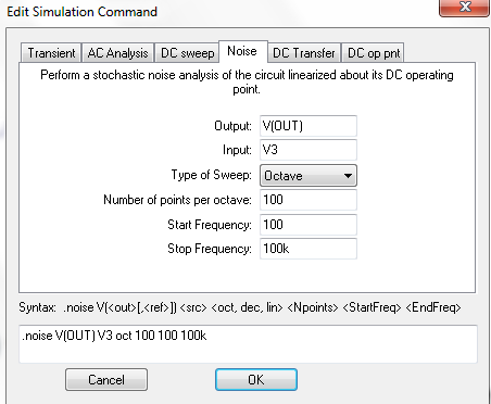
Figure 2
Note it is easier to configure the output noise if this node has a label. The output noise is calculated with respect to a noiseless input voltage which has to be defined. In this case it is the voltage source V3.
Running the simulation results in a noise of slightly over 4nV/√Hz as expected.
Running the simulation results in a noise of slightly over 4nV/√Hz as expected.
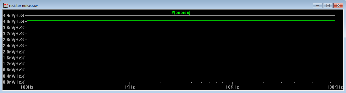
Figure 3
Op Amp Noise
OK, so how do we calculate the noise figure of a circuit using an op amp and resistors? Here, we need to consider the voltage and current noise of the op amp, the noise generated by the resistors as well as the gain in the circuit.
Figure 4 shows a non inverting op amp with unity gain.
OK, so how do we calculate the noise figure of a circuit using an op amp and resistors? Here, we need to consider the voltage and current noise of the op amp, the noise generated by the resistors as well as the gain in the circuit.
Figure 4 shows a non inverting op amp with unity gain.
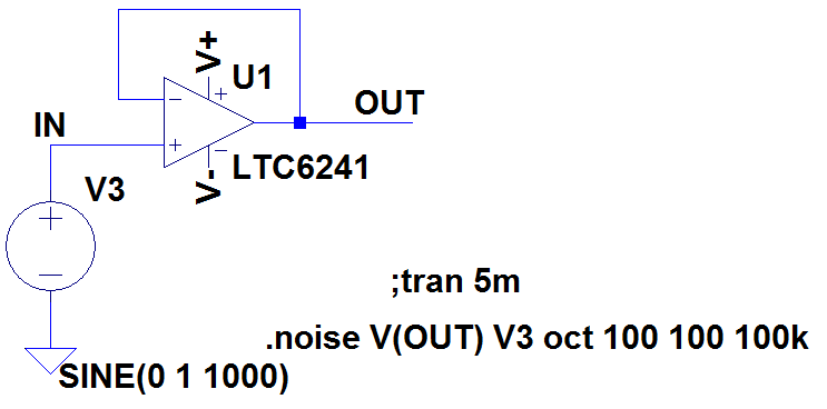
Figure 4
The circuit can be downloaded here: Non Inverting Op Amp Noise
The LTC6241 has an input noise voltage density of 7-10nV/√Hz and an input noise current density of 0.56fA/√Hz at 1kHz. Since we are driving both op amp inputs from a low impedance source, the current density is of no concern. However the input noise voltage density needs to be considered.
To calculate the noise of an op amp circuit, all inputs must be grounded. As we will see later, this makes the inverting configuration and the non inverting configuration identical. The input noise voltage of the op amp can be modelled as a voltage in series with the input as shown in Figure 5
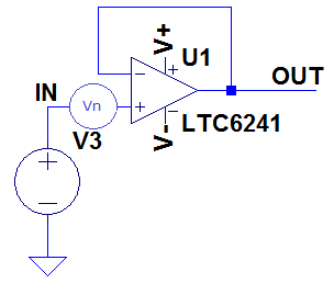
Figure 5
It is obvious that, with the input to the circuit grounded
Output Voltage Noise = Input Voltage Noise = 7nV/√Hz
and this is shown in Figure 6
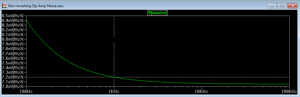
Figure 6
This circuit demonstrates the noise of the op amp without the effect of gain or external resistors. We can also see from this circuit that LTspice is working with an input voltage noise of 7.2nV/√Hz instead of the datasheet typical value of 7nV/√Hz.
We will now examine the effect that gain and external resistors have on the noise performance of the circuit. Figure 7 shows a non inverting amplifier stage with gain of 2
We will now examine the effect that gain and external resistors have on the noise performance of the circuit. Figure 7 shows a non inverting amplifier stage with gain of 2
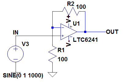
Figure 7
This circuit can be downloaded here: Non Inverting Amplifier Noise
We mentioned earlier that, in grounding the inputs to the circuit of Figure 7, both inverting and non inverting configurations are identical and this is now easy to see. There are 2 methods of calculating the output noise of the amplifier circuit.
Method 1
Method 1 uses a noise model of the circuit of Figure 7 as shown in Figure 8.
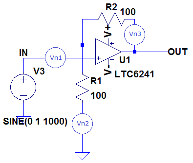
Figure 8
Vn1 represents the noise of the op amp itself (7.2nV/√Hz) and Vn2 represents the noise from the resistor R1. Now, we can see that the noise generated by R1 is effectively applied to the input of an inverting amplifier, so is subjected to the gain of the amplifier, in this case a gain of 1 (since noise as such has no phase, a gain of -1 is the same as a gain of +1). Vn3 represents the noise from resistor R2 and is not subject to any gain. The noise of the op amp itself is applied to the non inverting input of the amplifier, so is subject to a gain of +2.
To find the total noise (in nV/√Hz) we need to square the contributions of each noise source, sum them at the output, then take the square root. This looks complicated, but only involves simple (if a little tedious) mathematics.
From the equation at the top of the page, a 100 Ohm resistor produces noise of 1.28nV/√Hz.
Therefore the total noise resulting from op amp voltage noise and resistor noise, seen at the output of the amplifier circuit in Figure 8 is:
√{ (7.2nV/√Hz x 2)2 + (1.28nV/√Hz x 1)2 + (1.28nV/√Hz)2} = 14.5nV/√Hz.
We now need to consider the effect of the op amp’s current noise. Since our non inverting input is grounded (for the purpose of noise analysis), the input noise current (0.56fA/√Hz) can be modelled as flowing into the inverting input. Since the non inverting input is grounded and we have negative feedback around the amplifier, the inverting terminal is at a virtual earth. Therefore the current noise of the op amp only flows through the feedback resistor. From Ohm’s law, it produces a voltage of
(R2 x i_noise) = 100 x 0.56fA/√Hz = 56fV/√Hz.
Even though this is negligible, to get an accurate calculation of the total output noise, we need to square this voltage and add it to the square of the voltage noise calculated above.
Thus our total noise is
Thus our total noise is
√{ (14.5nV/√Hz)2 + (56fV/√Hz)2} = 14.5nV/√Hz
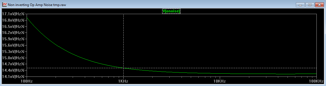
Figure 9
An LTspice simulation of the circuit shows the result to be 14.5nV/√Hz.
Method 2
Picturing where to put the noise sources in the feedback components of the amplifier can be tricky. Therefore Method 2 might prove more intuitive and easier to visualise. Considering again the circuit in Figure 7, if all the inputs are grounded then the output will be at 0V too. Thus the feedback resistor R2 is effectively in parallel with R1. With this in mind, we end up with the noise equivalent circuit shown in Figure 10
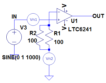
Figure 10
Here the feedback resistor and the input resistor are in parallel and the resistor noise is calculated by using the parallel resistance value. However, with this approach the noise is applied to the inverting input of the op amp, but with no feedback resistor. All is not lost however, as applying a voltage to the inverting op amp input is the same as applying the same voltage to the non inverting pin of the amplifier since as stated earlier we are not concerned about phase. Thus applying the noise voltage to the non inverting input subjects the noise to a gain of (1+R2/R1). Thus our voltage noise is calculated as
√{ (7.2nV/√Hz x 2)2 + (0.907nV/√Hz x 2)2} = 14.5nV/√Hz
Where 0.907nV/√Hz is the noise of two 100 Ohms resistors in parallel. This yields the same voltage noise as in Method 1.
Likewise, any noise current flowing into the inverting terminal will produce a voltage across the parallel combination of R2 and R1. This is the same as applying a noise voltage to the non inverting terminal and subjecting it to a gain of (1+ R2/R1), thus the 'current' noise is:
Likewise, any noise current flowing into the inverting terminal will produce a voltage across the parallel combination of R2 and R1. This is the same as applying a noise voltage to the non inverting terminal and subjecting it to a gain of (1+ R2/R1), thus the 'current' noise is:
(100||100) x 0.56fA/√Hz x 2 = 56fV/√Hz
This yields the same current noise as in Method 1.
The total noise is
The total noise is
√{(14.5nV/√Hz)2 + (56fV/√Hz)2} = 14.5nV/√Hz
We have discussed how to calculate the output noise of an op amp and seen how this is dependent on the voltage and current noise specs of the amplifier as well as the gain and the surrounding resistors.
It is worth repeating the above with resistors of 1k, 10k and 100k and these are tabulated below
It is worth repeating the above with resistors of 1k, 10k and 100k and these are tabulated below
This clearly shows that the noise figure of the op amp is not done justice if the gain setting resistors are large. To ensure you get the noise performance you paid for, keep the gain setting resistors as low as the amplifier will allow.
LTspice is a registered trademark of Analog Devices Inc
Sitemap: www.simonbramble.co.uk/sitemap
© Copyright Simon Bramble