Wien Bridge Sine Wave Oscillators
This article explains how a Wien Bridge oscillator works and how it can be used to design a sinewave oscillator.
Introduction
One of the simplest sinewave oscillators is the Wien Bridge Oscillator. Any circuit requires 2 conditions to oscillate. Tracing the path from the input, round the feedback network, back to the input there must be an overall phase shift of 0 degrees at one particular frequency. In other words, any signal travelling around this loop, must be in phase with the original signal as it arrives back at the input and thus add to the input signal.
As the signal travels around the loop, there will be a loss in the system (heat dissipation in the components, losses in the amplifier etc). Therefore there must be some form of gain in the loop, such that the signal arriving back at the input (having travelled around the loop) is equal to or larger than the original signal. If these 2 conditions are met, the oscillations will be sustained.
Figure 1 shows a typical Wien bridge oscillator. The circuit relies on the series RC network (made up of R1 and C1) and the parallel RC network (made up of R2 and C2) causing a phase shift of 0 degrees at one particular frequency at the non inverting input. Thus from what we have said, taking the signal at the + input, through the op amp, through R1 and C1 and back to the + input causes a phase shift of 0 degrees at one particular frequency.
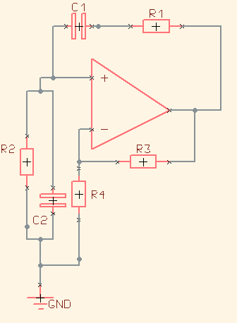
Figure 1
The feedback resistors R3 and R4 around the inverting input set the gain to maintain oscillation.
The following involves some equations that look a bit hair raising, but if you compare Figure1 with a normal non inverting op amp circuit and have a rough grasp of how capacitors vary their characteristics with frequency, you should be able to follow them.
An easy way of analysing this circuit is to consider the gain and phase shift caused by the Wien bridge network (the series and parallel RC components) and ignore the other components in the circuit, as shown in Figure 2

Figure 2
The series RC circuit (R1 and C1) has an impedance:
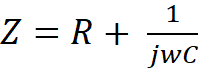
w is the frequency and is simply equal to 2πf (where f is the frequency in Hertz)
The term is the impedance of the capacitor. The j term represents a phase shift. When combined with the frequency term, w, implies we have an impedance that changes over frequency. These are obviously fundamental to the operation of our oscillator.
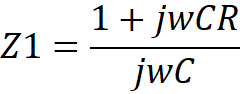
So multiplying top and bottom by jwC gives
The
term is the impedance of the capacitor. The j term represents a phase shift. When combined with the frequency term, w, implies we have an impedance that changes over frequency. These are obviously fundamental to the operation of our oscillator.So multiplying top and bottom by jwC gives
Likewise, the parallel RC network (R2 and C2) has an impedance
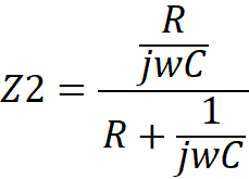
The parallel combination of 2 resistors is equal to the product divided by the sum of the resistors. The same is true with a parallel combination of a resistor and a capacitor.
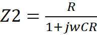
The overall impedance of the parallel network is simply the product divided by the sum of the capacitor impedance and the resistance
Multiplying top and bottom by jwC gives:
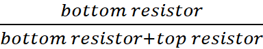
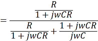
Now, the transfer function of a resistor divider is equal to:
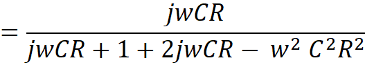
So the transfer function then becomes of our Wien network becomes:

Now, to keep the maths simple, we assume that both the capacitors are the same value (and put them equal to C) and both resistors are the same value (and put them equal to R).

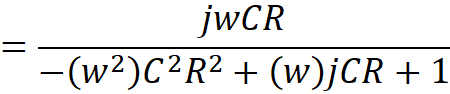
From here we can see that at
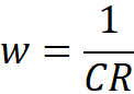 , the transfer function becomes:
In other words, the gain from the output to the non inverting input is 1/3.
As the j terms cancel out, there is no phase shift – i.e. there is no j term on the top or the bottom of the above number. We therefore have zero phase shift from output to input, so we have achieved half of our criteria for oscillation
We know that for oscillation to occur, the gain of the loop has to be 1 so we need to have a gain of 3 to overcome the ‘loss’ of 1/3 going from output to input.
With a simple op amp circuit, if an input is applied to the non inverting terminal (+) then the feedback resistor (R3 in FIG 1) has to be twice R4 to get a gain of 3 since

The same is true with the oscillator circuit. To get a gain of 3, R3 has to be exactly 2x R4. This has to be maintained throughout the entire operation of the circuit so a certain amount of variability has to be built into the gain components. We also need a gain of >3 to start the circuit up, then the gain must limit to 3 to maintain correct operation. To achieve this, a transistor is normally placed in the position of R4 that changes its resistance according to output voltage. As the output grows its resistance increases to reduce the overall gain.
Thus we have achieved conditions for oscillation – gain of 1 with a phase shift around the loop of zero.
Sitemap: www.simonbramble.co.uk/sitemap
© Copyright Simon Bramble