LTspice Tutorial: Part 4
This LTspice Tutorial explains how to import third party models into LTspice®.
LTspice is not limited to simulating Linear Technology parts. Third party models can be imported into LTspice too. There are 2 types of model that can be imported into LTspice:
.MODEL parts - these are simple components such as transistors and diodes
.SUBCKT parts - these are more complex parts made up of simpler SPICE parts (diodes, transistors, resistors etc, usually defined by a .MODEL statement)
It is important to note that LTspice looks at the first line of the SPICE model to determine how the model should be handled. If the part is defined with a .MODEL statement, importing the model is handled one way; if the part is defined with a .SUBCKT statement, importing the model is handled in a slightly different way. Thus we could import 2 identical diodes, one defined with a .MODEL statement and one defined with a .SUBCKT statement and they are actually handled differently. LTspice looks at the model definition, NOT the component to determine how to import the part.
.MODEL parts:
To import a simple third party SPICE model into LTspice using the .MODEL directive , follow these steps:
Here is an example of how to import a Schottky diode into a circuit. FIG 1 shows a simple circuit to measure the forward voltage drop across a diode. This can be downloaded here: Diode Test Circuit
LTspice is not limited to simulating Linear Technology parts. Third party models can be imported into LTspice too. There are 2 types of model that can be imported into LTspice:
.MODEL parts - these are simple components such as transistors and diodes
.SUBCKT parts - these are more complex parts made up of simpler SPICE parts (diodes, transistors, resistors etc, usually defined by a .MODEL statement)
It is important to note that LTspice looks at the first line of the SPICE model to determine how the model should be handled. If the part is defined with a .MODEL statement, importing the model is handled one way; if the part is defined with a .SUBCKT statement, importing the model is handled in a slightly different way. Thus we could import 2 identical diodes, one defined with a .MODEL statement and one defined with a .SUBCKT statement and they are actually handled differently. LTspice looks at the model definition, NOT the component to determine how to import the part.
.MODEL parts:
To import a simple third party SPICE model into LTspice using the .MODEL directive , follow these steps:
- Add a generic component to the schematic that represents the symbol of the SPICE model
- Download the SPICE model into the same directory as the circuit you are simulating
- Make a note of the filename of the SPICE model, including the file extension
- Add a .include SPICE directive to the schematic that will use the model
- Open the SPICE model and note the name of the model - this is the text immediately after the .MODEL directive and before the part designator (in the case below this is the text DI_SBG1030L). The SPICE model can be viewed from within LTspice
- Press <CTRL> then right click over the generic component and change the 'Value' field to the SPICE model name
- Ensure the .include SPICE directive contains the exact filename of the SPICE model
- Ensure the name of the generic component exactly matches the SPICE model name
Here is an example of how to import a Schottky diode into a circuit. FIG 1 shows a simple circuit to measure the forward voltage drop across a diode. This can be downloaded here: Diode Test Circuit
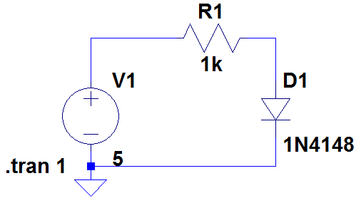
Figure 1
Running the simulation shows the diode has a forward voltage drop of 653.2mV
Remove diode D1 and replace it with the standard Schottky diode from the LTspice library.
Download the SPICE model of the BAT 54 Schottky diode: BAT 54 SPICE model and save it in the same directory as the circuit in Figure 1.
Add the following SPICE directive to your schematic using the symbol:
Remove diode D1 and replace it with the standard Schottky diode from the LTspice library.
Download the SPICE model of the BAT 54 Schottky diode: BAT 54 SPICE model and save it in the same directory as the circuit in Figure 1.
Add the following SPICE directive to your schematic using the
 symbol:
.include DI_BAT54.txt
To avoid spelling mistakes, use Windows Explorer to highlight and copy the filename including the filename extension (.txt). Paste the text after the include statement.
Open the SPICE model file (using, say, Notepad) and note the name of the model (in this case it is DI_BAT54). Again, to avoid spelling mistakes, it is easier to highlight the model name and copy it.
Press <CTRL> Right click over the Schottky diode symbol and paste the text DI_BAT54 into the Value field as shown in Figure 2. Do not put any comments in the Spice Model field.
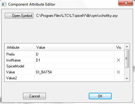
Figure 2
The final circuit should look like Figure 3
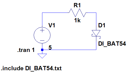
Figure 3
Run the simulation. The forward voltage drop should now be 290mV.
If you encounter errors, check the following:
- Has the SPICE file been loaded into the same directory as the simulation file?
- Is the part name the same as that specified in the SPICE model?
- Does the filename in the .include statement exactly match the SPICE model filename?
It is also worth opening the SPICE model file from within LTspice and checking its contents. Some text editors can add formatting characters that confuse LTspice.
.SUBCKT parts
A similar procedure can be used to import more complex models. Follow the steps above, except when modifying the Component Attribute Editor (see Figure 2), ensure the Prefix attribute is marked as X (and not D as in Figure 2).
We are now going to compare the performance of the LT6231, (215MHz low noise op amp) with the LM324 (low cost op amp).
Download the circuit in Figure 4: Op Amp Test Circuit
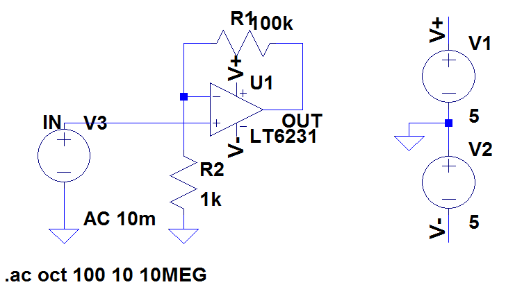
Figure 4
Running this circuit shows the output falls from 1V at dc to 0.707V at about 2.77MHz.
Now remove the LT6231 and replace it with a standard 5 terminal op amp. This is the 'opamp2' model in the Op Amps folder in LTspice.
Download the LM324 model and save it in the same directory as the circuit in Figure 4.
Make a note of the SPICE model filename (in this case it is LM324.txt). Add a .include SPICE directive in your schematic as follows:
.include LM324.txt
Open the SPICE model and make a note of the SPICE model name (immediately after the .SUBCKT command). In this case it is LM324.
Press <CTRL> Right click over the op amp symbol in the schematic and insert the model name into the Value field as shown in Figure 5
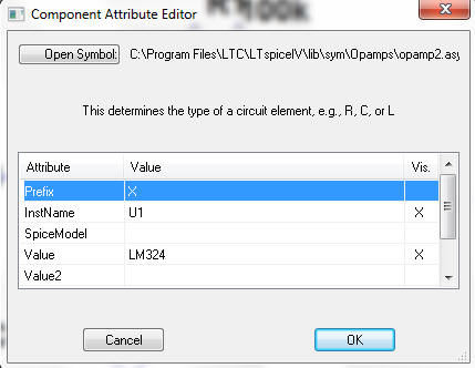
Figure 5
Ensure that the Prefix attribute is filled in with X.
NOTE: The SPICE model of some simple components (e.g. Zener diodes) are defined as a SUBCKT. In this case, the Prefix attribute has to be 'X' and not 'D' to correspond with the .SUBCKT SPICE definition (and not a .MODEL definition).
Creating a Quick Part Outline for 3rd Party SPICE models
Once the SPICE model has been imported, an outline can be created for the part. Open the SPICE model in LTspice, move the mouse over the .SUBCKT line, right click and select 'Create Symbol'. A square symbol will appear showing the nodes of the SPICE model.
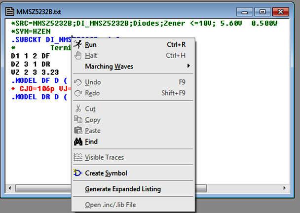
Figure 5a
Then select a new component (using the  symbol) and in the dialogue box, the new component is stored under the [AutoGenerated] directory.
Running the simulation shows the output falls to 0.707V at about 10kHz, showing the inferior frequency response of the LM324 over the LT6231.
The final circuit is shown in Figure 6.
 symbol) and in the dialogue box, the new component is stored under the [AutoGenerated] directory.
Running the simulation shows the output falls to 0.707V at about 10kHz, showing the inferior frequency response of the LM324 over the LT6231.
The final circuit is shown in Figure 6.
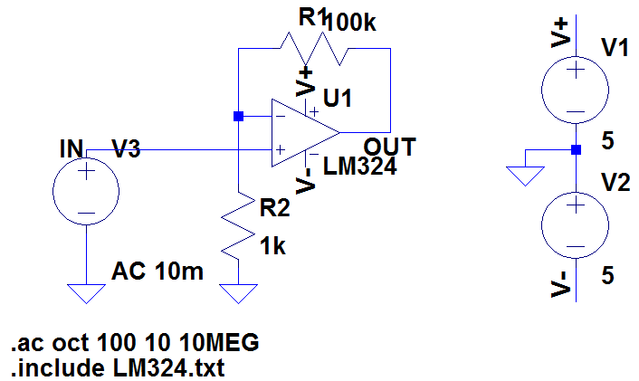
Figure 6
SPICE models for many components that are needed with LTC devices can be downloaded here:
Want to know more?
Please see LTspice Tutorial: Part 5
LTspice is a registered trademark of Analog Devices Inc
Please see LTspice Tutorial: Part 5
LTspice is a registered trademark of Analog Devices Inc
Sitemap: www.simonbramble.co.uk/sitemap
© Copyright Simon Bramble